Tips and tricks
This site tries to provide some code changes which could give you a nice extra feature. But which is not really used by many so not an official setting.
Get external LEDs and piezo buzzer working with Crius 1.1
The Crius board only allows you to connect A0 to A5 so the default config does not work.
Here are the code-changes necessary to still have external LEDs and a piezo buzzer.
config.h changes:
#define PIEZO_PIN 46
#define COPTER_LED_1 AN2 // Motor or Aux LED
#define COPTER_LED_2 AN3 // Motor LED
#define COPTER_LED_3 AN4 // Motor or GPS LED
#define COPTER_LED_4 AN7 // Motor LED
#define COPTER_LED_5 -1 // Motor LED
#define COPTER_LED_6 -1 // Motor LED
#define COPTER_LED_7 -1 // Motor LED
#define COPTER_LED_8 -1 // Motor LED
define.h changes:
#define AN5 46
// #define PIEZO_PIN 32 //Last pin on the back ADC connector
#define PIEZO_PIN 46
After this changes, a compile and flash you can connect the arming led on A3, the GPS led on A4 and the Buzzer on PIN 46.
You also need to set the Led Mode to 127 via Advanced parameters in the Mission Planner software.
Use an external compass instead of using the internal
Sometimes you want to use an external compass instead of the flight controllers on board one. In most cases its not really needed, but you have the option.
libraries\AP_InertialSensor\AP_InertialSensor_MPU6000_I2C.cpp changes:
//#define DISABLE_INTERNAL_MAG to #define DISABLE_INTERNAL_MAG
After this changes, a compile and flash you also need to erase and reset to factory defaults via Mission Planner.
Battery Voltage Meter on Analog PIN A1
That is just a hardware modification. Basicly you will need two resistors (R1 of 120k and R2 of 27k) hooked up like this:
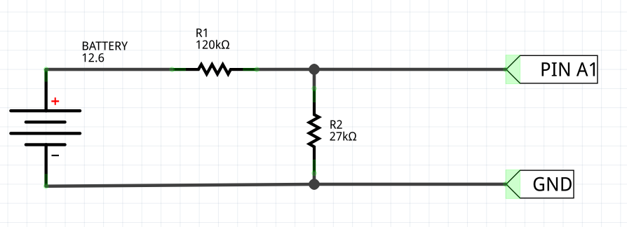
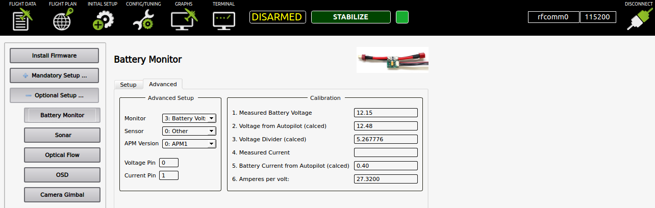
So now you can go to APM Planner -> Initial Setup -> Optional Setup -> Battery Monitor -> Advanced. There you change these stuff:
Monitor     => 3: Battery Voltage
Sensor      => 0: Other
APM Version => 0: APM1
Voltage Pin => 1
So now it will start measuring battery voltage. But you need to calibrate the software. So get a multimeter and measure the voltage across the battery. I recomend to use a fully charged battery (3s will give arround 12.6V and 4s will give you arround 16.4V). After you get a reference, write it on field 1. Measured Battery Voltage So now it should change automatically the parameter 3. Voltage Divider (calced) and start measuring the correct voltage on 2. Voltage from Autopilot (calced)
You can also use other Analog Ports ( I use A0 ) for Battery Measuring. Just change the Voltage Pin Number for that.
There is other stuff you can configure related to the Battery Voltage Monitor. For more details take a look on the oficial documentation for Power Module set-up to measure battery voltage and current consumption
RSSI input on analog PIN A0
config.h changes:
Around line 208 you will find:
#elif CONFIG_HAL_BOARD == HAL_BOARD_MPNG
 # define A_LED_PIN        13
Change to:
#elif CONFIG_HAL_BOARD == HAL_BOARD_MPNG
 # define RECEIVER_RSSI_PIN 0
 # define A_LED_PIN        13
parameters.ino changes:
Around line 192 you will find:
GSCALAR(rssi_pin, "RSSI_PIN", -1),
Change to:
GSCALAR(rssi_pin, "RSSI_PIN", RECEIVER_RSSI_PIN),
After that you can enable the RSSI_PIN via MissionPlanner.
To test if it works you can connect a 1.5v battery on A0